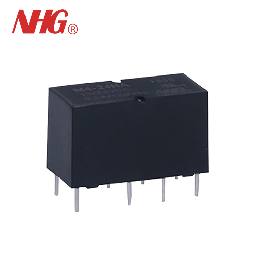
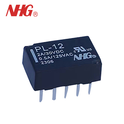
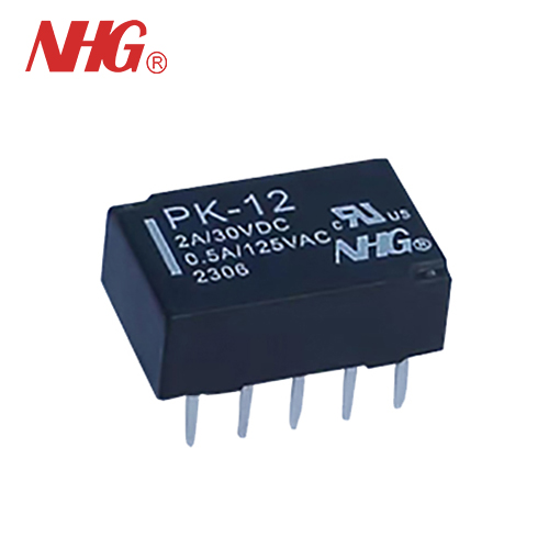
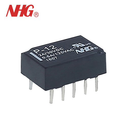
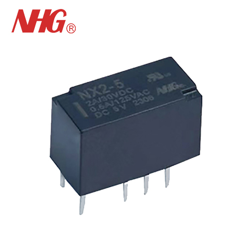
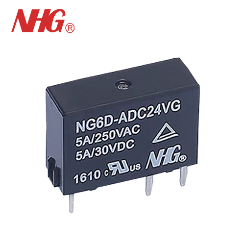
High Sensitive Bifurcated Contact Signal Relay
◉ Fully sealed for immersion cleaning ◉ High sensitivity:0.15mW nominal power consumption ◉ Conforms to fcc Part 68 1500v Surge and Dielectric 1000vac ◉ RoHS CompliantModel:M4
Send Inquiry
PDF DownLoad
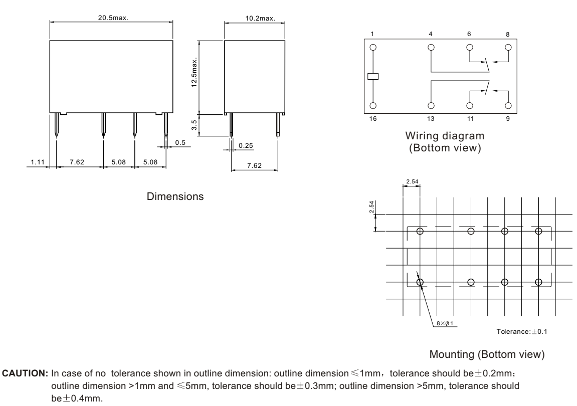
DIL pitch terminals. High sensitivity.
Conforms to FCC Part 68 1.5kV surge and dielectric 1000VAC.
High reliability bifurcated contact.
Application for telecommunication equipment, office equipment, security alarm systems, measuring instruments,medical monitoring equipment, audio visual equipment, flight simulator, sensor control.
Ordering Information

1 Part mumber: M4
2 Coil rated voltage: DC:3:3V; 5:5V; 6:6V; 9:9V ;
12:12V; 24:24V; 48:48V
3 Enclosure: H: Wash tight
4 Contact material: Nil: AgPd; W: AgNi
5 Nominal coil power: Nil:0.15W; A:0.2W
Contact Data
|
Contact Arrangement |
2C(DPDT(B-M)) (Bifurcated Crossbar) |
||
|
Contact Material |
AgPd(Au plated ) AgNi(Au plated) |
||
|
Contact Rating (resistive) |
1A/24VDC; 2A/30VDC; 0.5A/120VAC |
||
|
Max. Switching Power |
60W 125VA |
Min. Switching load:0.01mA/10mV(Reference Value) |
|
|
Max. Switching Voltage |
220VDC 250VAC |
Max. Switching Current:2A |
|
|
Contact Resistance |
≤50mΩ |
Item 4.12 of IEC 61810-7 |
|
|
Operational Life |
Electrical |
1A/24VDC:5X105 2A/30VDC 1X10⁵ 0.5A/120VAC:2X105 |
Item 4.30 of IEC 61810-7 |
|
Mechanical |
1X10⁸ |
Item 4.30 of IEC 61810-7 |
|
Relays previously tested or used above 10mA resistive at 6VDC maximum or peak AC open circuit are not recommended for subsequent use in low level applications.
Coil Parameter
|
Dash numbers |
Coil voltage VDC |
Coil resistance Ω±10% |
Pick-up voltage VDC(max) (70% of 66% of rated voltage ) |
Drop-out voltage VDC(min) (5% of 10% of rated voltage) |
Coil power W |
Operate time ms |
Release time ms |
|
|
Rated |
Max. |
|||||||
|
M4-003 |
3 |
7.5 |
60 |
2.1 |
0.15 |
0.15 |
Approx. 4.5 |
Approx. 1.5 |
|
M4-005 |
5 |
12.5 |
167 |
3.5 |
0.25 |
0.15 |
||
|
M4-006 |
6 |
15.0 |
240 |
4.2 |
0.3 |
0.15 |
||
|
M4-009 |
9 |
22.5 |
540 |
6.3 |
0.45 |
0.15 |
||
|
M4-012 |
12 |
30.0 |
960 |
8.4 |
0.6 |
0.15 |
||
|
M4-024 |
24 |
52.9 |
3840 |
16.8 |
1.2 |
0.15 |
||
|
M4-048 |
48 |
84.9 |
7680 |
33.6 |
2.4 |
0.30 |
||
|
M4-003A |
3 |
2.25 |
45 |
2.1 |
0.3 |
0.2 |
Approx. 4.5 |
Approx. 1.5 |
|
M4-005A |
5 |
4.5 |
125 |
3.5 |
0.5 |
0.2 |
||
|
M4-006A |
6 |
7.5 |
180 |
4.2 |
0.6 |
0.2 |
||
|
M4-009A |
9 |
9.0 |
405 |
6.3 |
0.9 |
0.2 |
||
|
M4-012A |
12 |
13.5 |
720 |
8.4 |
1.2 |
0.2 |
||
|
M4-024A |
24 |
18.0 |
2880 |
16.8 |
2.4 |
0.2 |
||
|
M4-048A |
48 |
36.0 |
11520 |
33.6 |
4.8 |
0.2 |
||
CAUTION:
1.The use of any coil voltage less than the rated coil voltage will compromise the operation of the relay.
2.Pickup and release voltage are for test purposes only and are not to be used as design criteria.
3.Unless otherwise stated, the rated coil voltage specified in coil parameter table shall be used for all tests and its application to the relay.
Characteristics
|
Electrostatic Capacitance |
|
|
|
Between Open Contacts |
Approx.0.7pF |
Item 4.41 of IEC 61810-7 |
|
Between Coil & Contacts |
Approx.1.0pF |
Item 4.41 of IEC 61810-7 |
|
Between Contact Poles |
Approx.0.9pF |
Item 4.41 of IEC 61810-7 |
|
Insulation Resistance |
1000MΩ min (at 500VDC) |
Item 4.11 of IEC 61810-7 |
|
Dielectric Strength |
|
|
|
Between Open Contacts Between Coil & Contacts Between Contact Poles |
1000VAC 1min 1000VAC 1min 1000VAC 1min |
Item 4.9 of IEC 61810-7 |
|
Surge Withstand Voltage |
|
|
|
Between Open Contacts Between Coil & Contacts Between Contact Poles |
1500V 1500V 1500V |
FCC 68 |
|
Shock Resistance |
Functional:98m/s² 211ms; Destructive:980 m/s² 26ms |
Item 4.26 of IEC 61810-7 |
|
Vibration Resistance |
10Hz-55Hz Double amplitude Functional:1.5mm Destructive:5mm |
Item 4.28 of IEC 61810-7 |
|
Terminals Strength |
5N |
Item 4.24 of IEC 61810-7 |
|
Temperature Range |
-40℃-90℃(-40° F~194° F) (-40℃〜80℃for 0.3W Coil) |
|
|
Mass |
Approx. 4.8g |
Item 4.7 of IEC 61810-7 |
Safety Approvals
