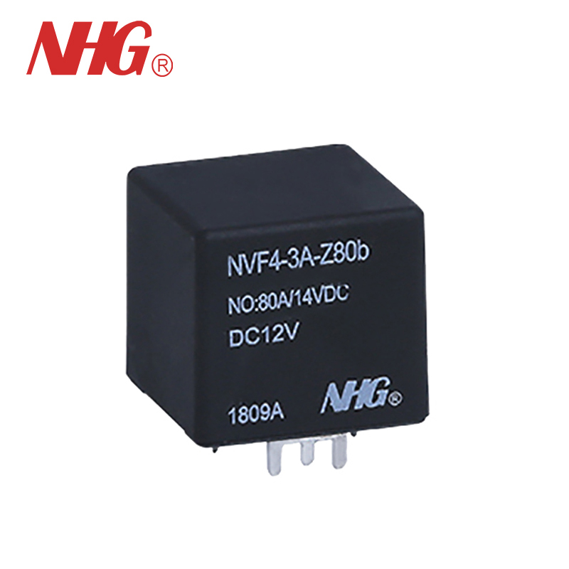
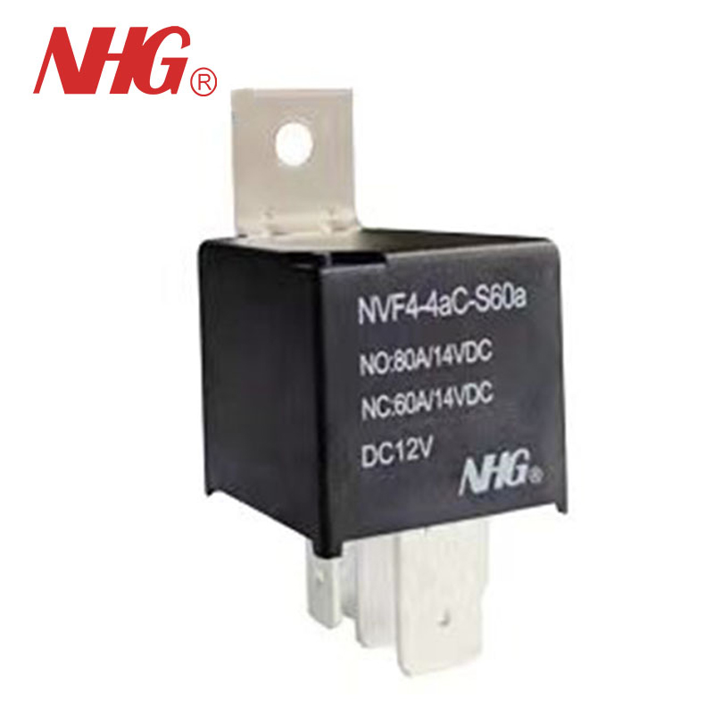
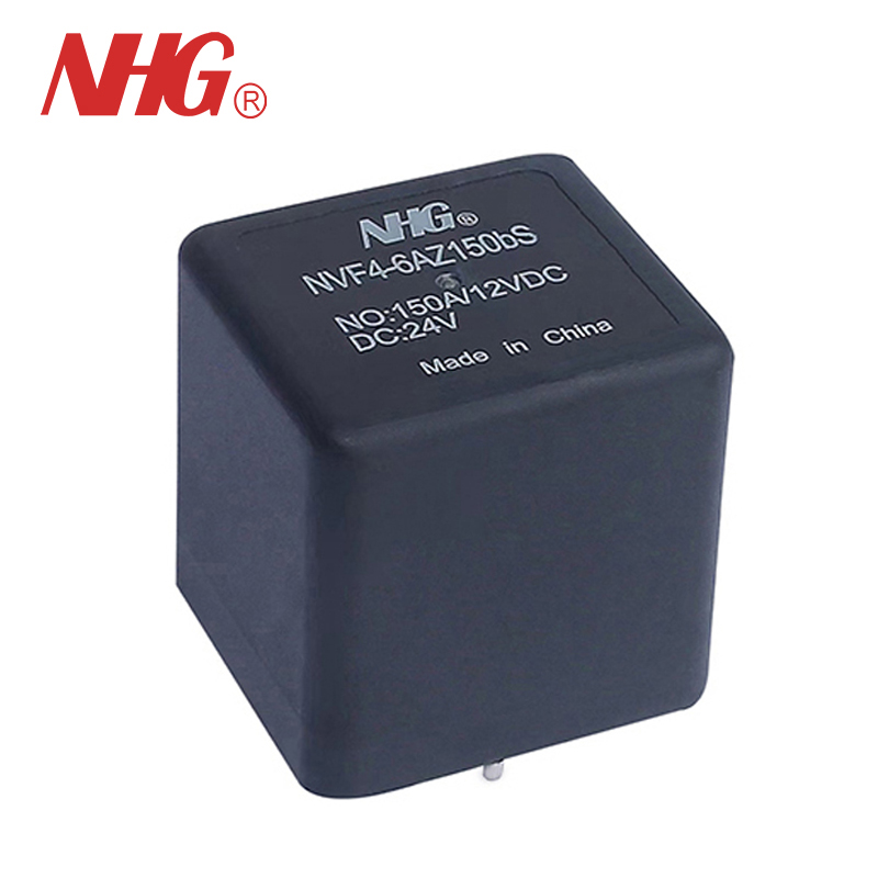
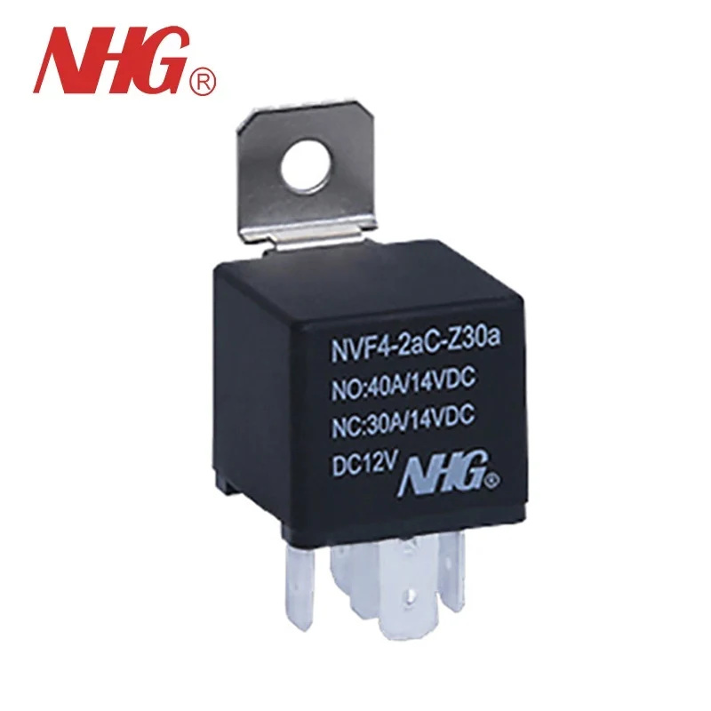
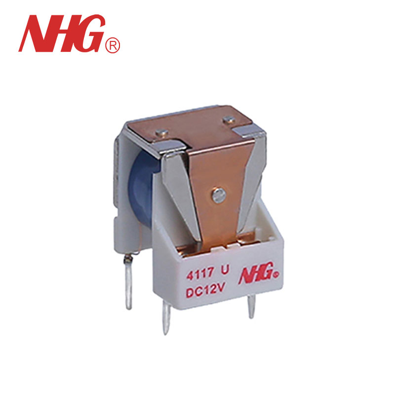
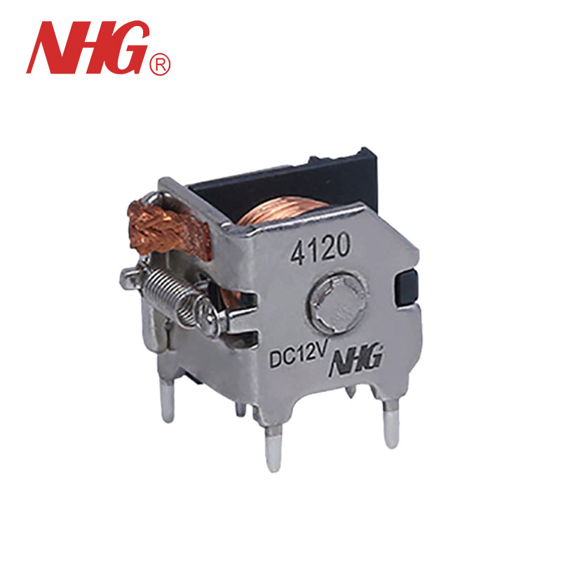
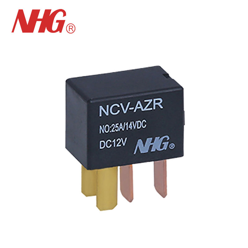
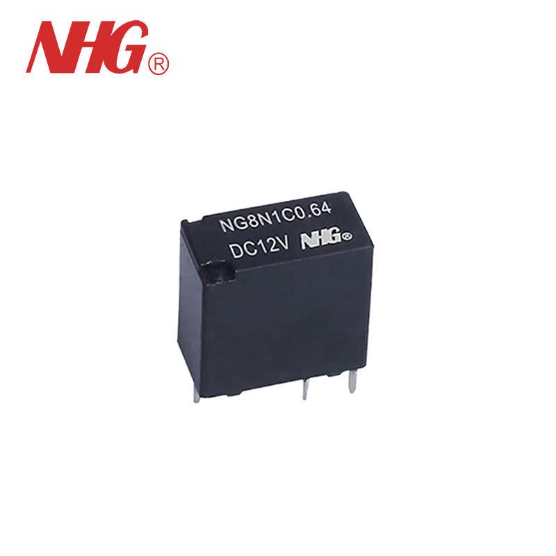
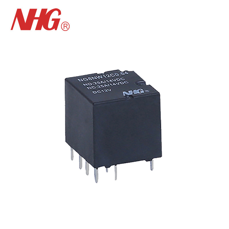
General Purpose With Bracket Automotive Power Relay
◉ Standard ISO terminal footprint ◉ 24V version with contact gap >0.8mm ◉ Wide temperature range : -40°C to 125° C ◉ Plastic sealed and flux proofed types available ◉ RoHS CompliantModel:NVF4-2
Send Inquiry
PDF DownLoad
Heavy contact load (40A).
Suitable for automobile and lamp accessories application.
PC board mounting and direct insert mounting available.
Ordering Information

1 Part number:NVF4-1
NVF4-2(Plastic Bracket),
NVF4-2a(With Metal Bracket)
NVF4-2b(Shrouded With Metal Bracket
2 Contact arrangement:A:1A1; A2:1A2; B:1B; C:1C;C2:1C2
3 Enclosure:S: Wash tight; Z: Dust protected
4 Contact current:A Form:20A,40A;
B Form: 20A,30A;
C Form or C2 Form: 15A,20A, 30A, 40A;
A2 Form: 2 20A
5 Terminals:b: PCB type; a1: plug in type 1; a2:plug in type 2
6 Coil rated voltage(V):DC:6,12,24,48
7 Coil power:1.6:1.6W; 1.9:1.9W
2.3:2.3W; 2.6:2.6W
8 Coil transient suppression: D: with diode
R: with resistance
NIL: standard
Contact Data

NOTE Limiting continuous current at 125 :NC/NO:10A/15A.
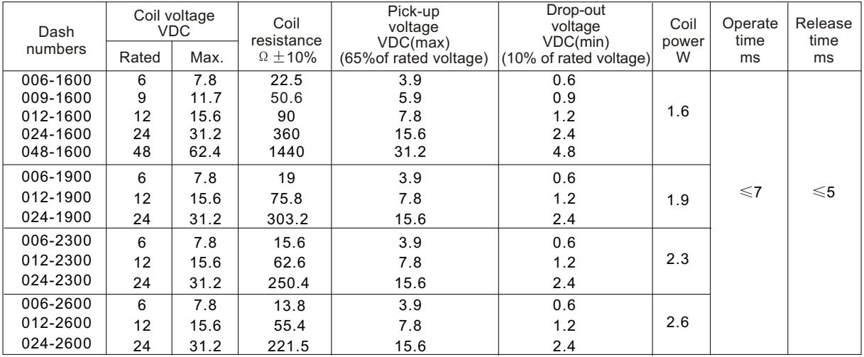
Coil Parameter
CAUTION:
1.The use of any coil voltage less than the rated coil voltage will compromise the operation of the relay.
2.Pickup and release voltage are for test purposes only and are not to be used as design criteria.
Characteristics
|
Insulation Resistance11 |
100MΩ min (at 500VDC) |
Item 4.11 of IEC 61810-7 |
|
Dielectric Strength1> Between Contacts Between Contact and Coil |
50Hz 500V 50Hz 750V |
Item 4.9 of IEC 61810-7 Item 4.9 of IEC 61810-7 |
|
Shock Resistance |
147m/s² 11ms |
Item 4.26 of IEC 61810-7 |
|
Vibration Resistance |
10Hz-40Hz Double amplitude 1.5mm |
Item 4.28 of IEC 61810-7 |
|
Terminals Strength |
Terminal retention(pull & push):2100N Terminal resistance to bending(front & side):,10N |
Item 4.24 of IEC 61810-7 |
|
Ambient Temperature |
-40℃~125℃ |
|
|
Relative Humidity |
5% to 85% |
Item 4.16 of IEC 61810-7 |
|
Mass |
31g(NVF4-1);33g(NVF4-2);33g(NVF4-2a);45g(NVF4-2b) |
Item 4.7 of IEC 61810-7 |
Note: 1). When testing, coil terminals should be connected, If coil transient suppression is installed in relay .
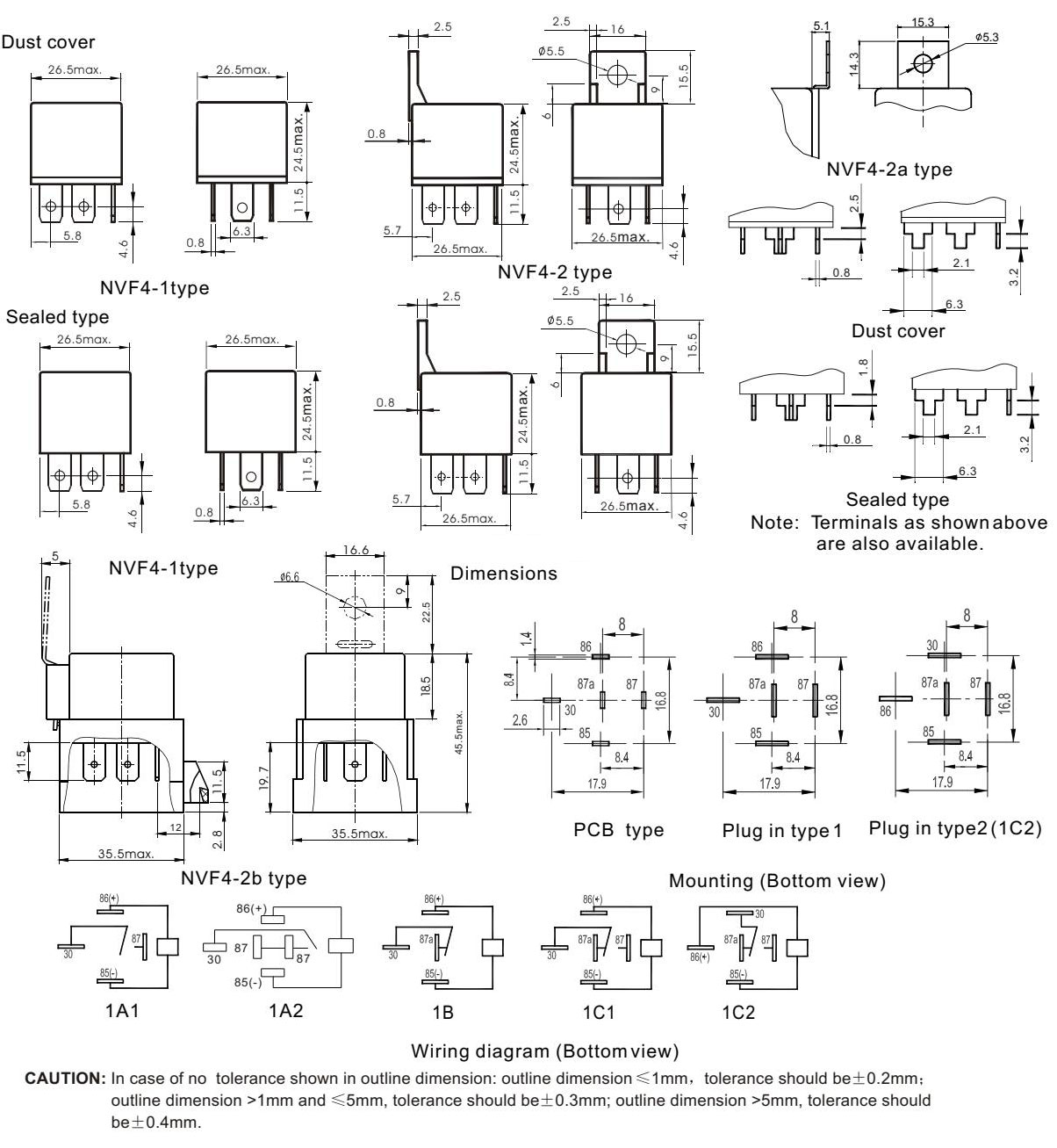
Dimensions
Reference Data


